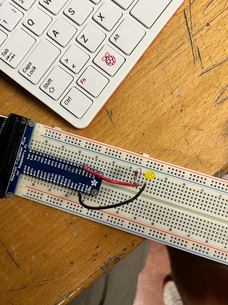
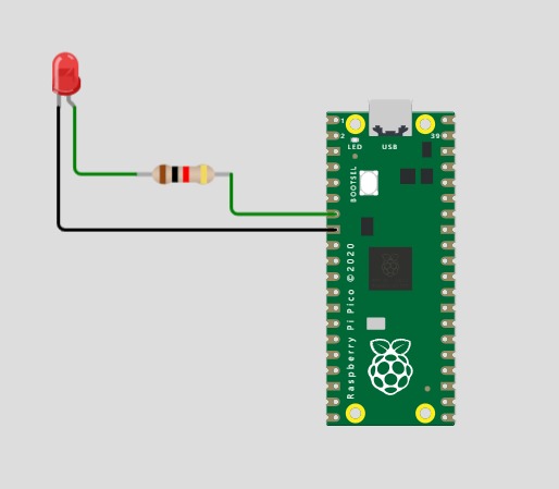
The first project we embarked on with the Raspberry Pi 4 was a classic: the Raspberry Pi Hello World. In this case, our Hello World involved turning on an LED. It's a popular starting point for many Raspberry Pi enthusiasts as it helps ensure the basic setup is functioning correctly.
For this project, we connected an LED to the Raspberry Pi and wrote a simple code to illuminate it. It served as a basic test to confirm that the Raspberry Pi was working properly and that we had successfully connected the components.
However, during the initial setup, we encountered a small hurdle. We initially struggled with connecting the resistor and the LED correctly. Fortunately, we quickly identified and rectified the issue, and it didn't pose a significant challenge.
By starting with the Hello World project of turning on an LED, we gained hands-on experience with the Raspberry Pi 4 and built a solid foundation for more complex projects. It was an excellent introduction to the capabilities of the Raspberry Pi and motivated us to explore further.
       import gpiozero
       from gpiozero import LED
       grnLed = LED(18)
       grnLed.off()
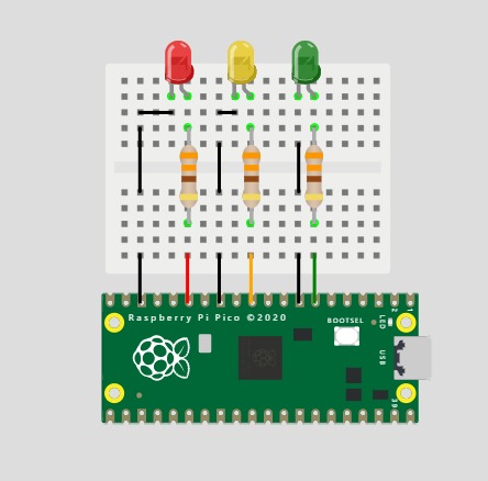
Our next milestone involved the implementation of a traffic light system. To achieve this, we connected three LEDs to the Raspberry Pi, each equipped with its own resistor. The LEDs were carefully selected to represent different colors: green, yellow, and red, mimicking the standard configuration of a typical traffic light.
Initially, we encountered an issue where all the LEDs blinked simultaneously, which hindered the proper functioning of the traffic light. However, through meticulous troubleshooting and experimentation, we successfully resolved the problem by introducing the concept of "delay" between the LED transitions.
To implement the delay, we incorporated the use of the "time.sleep" function. This allowed us to introduce a specific duration of pause between each LED state change, effectively simulating the timing sequence of a traffic light. By synchronizing the durations of the delays, we achieved a smooth and realistic transition between the different colored LEDs.
With the delay mechanism in place, the traffic light system now operates flawlessly. Each LED illuminates in sequence, accurately replicating the behavior of a real-world traffic light. This significant achievement brings us one step closer to creating a fully functional and interactive traffic management system using the Raspberry Pi.
    from gpiozero import LED
    import time
    from time import sleep
    ledred = LED(18)
    ledyellow = LED(16)
    ledgreen = LED(25)

    ledred.blink(on time-2, off time=2)

    ledyellow.blink (on_time=0.5, off_time=0.5)

    ledgreen.blink(on_time=2, off_time=2)


    while True:

    ledred.on()

    time.sleep(2)

    ledred.off()

    ledyellow.on()

    time.sleep(0.5)

    ledyellow.off()

    ledgreen.on()

    time.sleep(2)

    ledgreen.off()
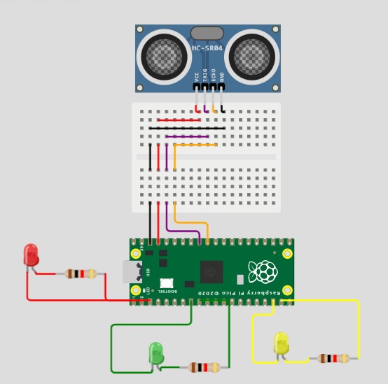
We have developed a pedestrian traffic light system using a Raspberry Pi microcomputer. The main objective of this system is to signal pedestrians when it is safe to cross a designated area. To accomplish this, we have employed an HCSR043 proximity sensor along with three colored LEDs: green, yellow, and red. In addition, we have integrated three resistors and several cables for seamless connectivity.
By utilizing the Thonny IDE, we have programmed the Raspberry Pi to dynamically change the color of the traffic light based on the distance measured by the proximity sensor. As an individual approaches the sensor, the traffic light switches to green, indicating that it is safe to proceed. When the person is at an intermediate distance, a yellow light is displayed as a cautionary signal. Lastly, if the person is far from the sensor, the traffic light exhibits a red light, signifying that they should wait before crossing.
This project serves as a valuable tool for constructing a pedestrian-focused traffic light system that offers a clear and visually discernible indication of when it is safe to cross. By leveraging the Raspberry Pi's flexibility and programming capabilities, we have successfully accomplished our objective.
from gpiozero import LED

import time

from time import sleep

from gpiozero import Distance Sensor

ledred = LED(18)

ledyellow = LED(16)

ledgreen = LED(25)

sensor DistanceSensor (echo=26, trigger=13)

while True:

distance = sensor.distance * 100

print('Distance: ', distance)

if distance < 4:

 ledyellow.off()

 ledgreen.on()

 ledred.off()

elif distance < 10:

 ledred.off()

 ledyellow.on()

 ledgreen.off()

else:

 ledred.on()
 ledyellow.off()
 Ledgreen.off()

sleep(0.1)
Example of the operation of our traffic light here:
.jpeg)
With an AI we have represented how it would be visually and how this traffic light works, in which it can be seen that each time it approaches the zebra crossing, the color of the traffic light will change.

We have used a tool called Bluedot to establish a Bluetooth connection between a mobile phone and a Raspberry Pi 4. Bluedot is a Python library that provides a simple and user-friendly interface for communicating with Bluetooth devices from the Raspberry Pi.
To start, we installed and configured Bluedot on both the Raspberry Pi and the mobile phone. Then, we created a small application on the Raspberry Pi using the Python programming language and the Bluedot library. This application allows us to control an LED connected to the Raspberry Pi.
On the mobile phone, we installed a complementary application called Bluedot Control, which provides a graphical interface for interacting with the Raspberry Pi via Bluetooth. From this application, we can send commands to the Raspberry Pi to turn the LED on or off.
When we start the application on the mobile phone and establish the Bluetooth connection with the Raspberry Pi, we can simply tap a button on the graphical interface of the application to turn the LED connected to the Raspberry Pi on or off.
We have used the same configuration as we used in the "Hello World"
from bluedot import BlueDot
import RPi.GPIO as GPIO

LED_PIN = 18

GPIO.setmode(GPIO.BCM)
GPIO.setup(LED_PIN, GPIO.OUT)

bd = BlueDot()

def encender_led():
    GPIO.output(LED_PIN, GPIO.HIGH)

def apagar_led():
    GPIO.output(LED_PIN, GPIO.LOW)

bd.when_pressed = encender_led
bd.when_released = apagar_led

bd.wait()
We decided to work with a Sense HAT as a final step. The Sense HAT is an expansion board specifically designed for the Raspberry Pi. It provides a variety of built-in sensors and devices that allow the Raspberry Pi to interact with the physical environment. Some of these components include an accelerometer, a gyroscope, a magnetometer, an LED matrix, and temperature, humidity, and pressure sensors.
With the Sense HAT, you can undertake various projects related to environment sensing and monitoring. For example, you can create a weather station that uses the temperature, humidity, and pressure sensors to collect data and display real-time local weather conditions. You can also develop games and add interactivity using the Sense HAT's LED matrix. Additionally, the accelerometer, gyroscope, and magnetometer sensors enable motion tracking and orientation monitoring, which can be useful in virtual reality, robotics, or navigation projects. The LED matrix can also be used to visually represent data, such as graphically displaying temperature, humidity, or other relevant information.
However, we encountered an issue when trying to connect the Sense HAT to the Raspberry Pi. Both the Raspberry Pi cable and the Sense HAT cable were female connectors, so they couldn't be directly connected. We didn't have a male-to-male cable available to make the connection, so we had to manually connect each of the 40 cables one by one to establish the complete connection between the two boards.
.jpeg)
.jpeg)
.jpeg)
.jpeg)